
Your shopping cart is currently empty.
T24 Wireless Sensor System
High accuracy, high quality measurement is interfaced with simple yet powerful configuration and monitoring software. T24 gives sensor manufacturers and integrators the complete flexibility to build their own sensor modules around it. The system easily replaces wired systems, reducing installation and maintenance costs.
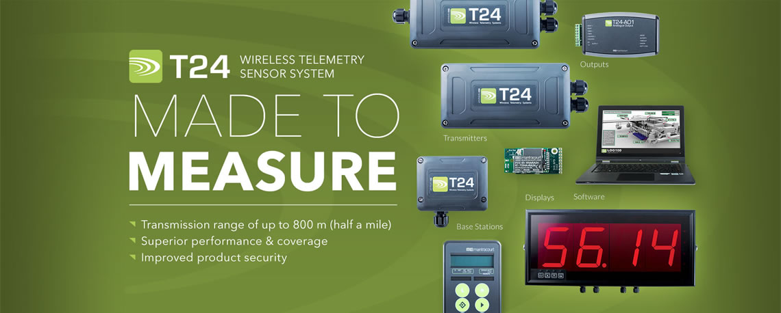
The T24 Wireless Telemetry Sensor System is a modular wireless solution for industrial sensor applications
Features & Benefits
High accuracy, high quality measurement is interfaced with simple yet powerful configuration and monitoring software. T24 gives sensor manufacturers and integrators the complete flexibility to build their own sensor modules around it. The system easily replaces wired systems, reducing installation and maintenance costs.
T24 Provides
T24 Provides
- Exceptional performance in the harshest of conditions
- High measurement low noise electronics
- Long battery life of up to five years in the field
- Proprietary license free 2.4 GHz
- Intuitive software which calibrates to sensors in under three minutes
Modular System
We know how industry applications can vary, so T24 can be constructed to fit around each requirement. Transmitter modules, base stations, robust handheld displays, serial outputs, relays, printers and analogue outputs can be simply configured to suit your needs.
Measurement Quality
High accuracy, low noise measurement electronics deliver high resolution, low drift results which can be user calibrated over nine points to enable linearisation and to deliver results in user definable engineering units. The results can be transmitted at rates of up to 200 per second to other T24 devices.
Powerful Software
Configuration of devices is simple with our user friendly Toolkit software. Configure and calibrate by using either known inputs or by table entry.
Range & Coverage
T24 modules are fitted with efficient antennas which provide superior performance and data integrity. The antenna’s signal integrity and coverage overcomes challenging environmental conditions such as moving objects or high metallic environments. The license free 2.4 GHz Direct Sequence Spread Spectrum (DSSS) radio technology offers high integrity, error free communications which can co-exist with other wireless technologies such as Wi-Fi, Bluetooth® and Zigbee®.
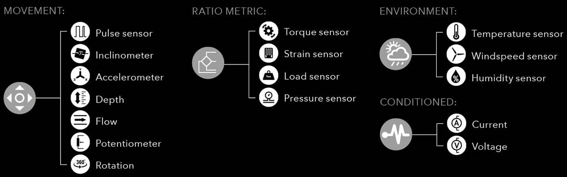
Instrumentation Designed for the Following Sensors
A Wireless Modular System
Construct systems to suit your application

PRODUCTS
T24 transmitter modules collect data from industrial sensors including load, pressure, torque, strain, temperature, pulse, potentiometer and 4-20 mA / 0-10 V conditioned sensors.
 Interfaces | Base Stations
Wireless base stations collect and configure data from T24 radio telemetry modules. Free software provides simplified configuration, logging and visualizations for Windows PCs.
 Outputs
Wireless receivers allow for data output to devices such as printers, loggers, PLCs and displays.
INDUSTRY APPLICATIONS
Construction
- Monitoring tension and compression on shoring struts
- Crane/under-hook scales
- Skip weighing
- Tension measurement on mooring lines
Energy
- Pressure sensing in gravity fed power station
- Strain measurement on wind turbine blades
- Torque measurement on rotating shaft
- Weight distribution on high performance vehicles
- Monitoring dynamic stresses on umbilical cords
Micron Meters customers find the T24 software fully functional and being laptop based makes it user-friendly and hassle free.
Our Technical Product Specialist and Engineers are always interested in finding new ways to incorporate the T24-Wireless Sensors into an application.
Challenge Us with your Application
Send us an email outlining your application and we will review it and reply with our recommendations.
Our Technical Product Specialist and Engineers are always interested in finding new ways to incorporate the T24-Wireless Sensors into an application.
Challenge Us with your Application
Send us an email outlining your application and we will review it and reply with our recommendations.
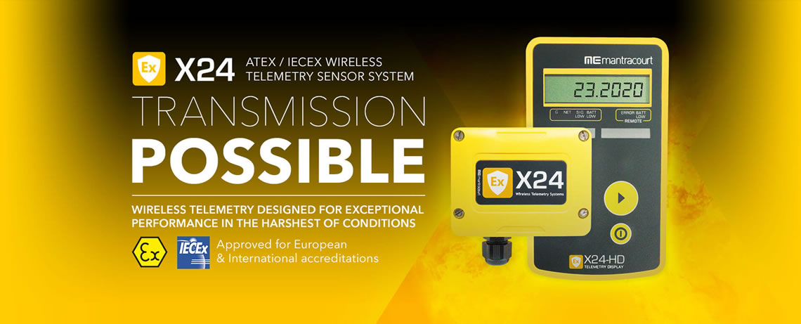
The X24 Wireless ATEX/IECEX Telemetry Sensor System is a modular wireless solution for Hazardous Zone applications
Features & Benefits
X24 Provides
- Intrinsically safe electronics approved for ATEX /IECEx Zones 1 & 2
- Adaptable and expandable wireless system for safe zones
- Long battery life of up to five years in the field
- Wireless transmission range of up to 800 m (half a mile)
- Proprietary license free 2.4 GHz, approved for FCC, IC and European use
- Intuitive software which calibrates to sensors in under three minutes
- Strain gauge measurements for load, strain, pressure, force and torque
Multiple usage scenarios
Certified wireless transmitters now available to cover multiple usage scenarios in potentially lucrative markets.
Intrinsically safe
Intrinsically safe electronics approved with the latest CSA Group / Sira Certification for ATEX / IECEx Zones 1 & 2.
Adapt to changing environments
Adapt to changing environments with an easy to add, expandable wireless system for new or retrofit installation. Certified transmitters send to ‘safe zone’ base stations, gateways, analogue and digital outputs.
Exceptionally reliable signal
Exceptionally reliable signal in environments which are likely to have a high density of metal equipment. High performance for assured and secured transmission. Reduce Installation and maintenance Installation costs vastly reduced with quick set up. Save on maintenance down time.
Up to half a mile Transmission distance
Transmission distance up to half a mile (800 m / 2600 ft) and battery lifetime of up to five years.
Enhance your Ex solution with trusted wireless technology
Benefit from our established, tried and tested technology designed and manufactured by the industry leader.
OEM option
OEM option for embedding within sensors and enclosures.
Free Logging and visualization software
Powerful logging and visualization software, which is entirely free to download from our website, is used to display and build visual representations of systems with live readings. Smart Diagnostics for Early Warning Intuitive software provides audible alarms to indicate under and over range as well as loss in communications. Indicates low battery and other remote sensor states and allows the creation of customized reports.
PRODUCT OVERVIEW
X24–HD
The X24-HD is a highly configurable ATEX/IECEx handheld display capable of working with X24 or T24 Transmitter modules. This allows wireless remote viewing of various remote inputs such as strain gauge or voltage etc. using 2.4 GHz radio.
X24–ACMi–SA
ATEX/IECEx Telemetry transmitter module in an enclosure which measures strain input and periodically transmits data for receipt by X24 or T24 receivers.
X24-SAe ATEX/IECEx
Telemetry transmitter OEM module measures strain input and periodically transmits data for receipt by X24 or T24 receivers.
Support-T24 Wireless Sensor System
Technical Support Documents for our products are available in Adobe PDF file format.A free copy of Adobe PDF Reader can be downloaded direct from Adobe by Clicking Here .
Document Downloads (PDF)
- T24 Enclosure Comparison
- T24 Telemetry User Manual:T24 Users Manual (ALL PRODUCTS) 8.3MB
- T24 WSS Data Sheet : Wireless Wind-speed Transmitter
- T24-HS Product Sheet : Handheld Telemetry Display with Multiple Inputs
- T24-HA Product Sheet : Handheld Telemetry Display with Multiple Inputs
- T24-HR Product Sheet : Handheld Telemetry Display with Multiple Inputs
- T24-LD1 Product Sheet :Wireless Telemetry Large LED Display T24-LD1
- T24-BSu Product Sheet : Wireless Telemetry USB Radio Base Station
- T24-BSue Product Sheet : Wireless Telemetry USB Radio Base Station
- T24-BSi Product Sheet : Wireless Telemetry Radio Base Station
- T24-GW1 Product Sheet : Wireless Telemetry Modbus Gateway
- T24-AO1 Product Sheet : Wireless Analogue Output Module
- T24-RM1 Product Sheet : Wireless Data Relay Module
- T24-S0 Product Sheet : Wireless Data Relay Module
- T24-RDC Product Sheet : Wireless Data Collector
- T24-PR1 Product Sheet : Wireless Telemetry Printer
- T24-IA Product Sheet : Wireless Telemetry Current 0-20mA Acquisition Module
- T24-PA Product Sheet : Wireless Telemetry Pulse Acquisition Module
- T24-RA Product Sheet : Wireless Telemetry Potentiometer Acquisition Module
- T24-SA Product Sheet : Wireless Telemetry Strain Gauge Acquisition Module
- T24-SAf Product Sheet : Wireless Telemetry Strain Gauge Acquisition Module 2Khz
- T24-TA Product Sheet : Wireless Telemetry Temperature Acquisition Module
- T24-VA Product Sheet : Wireless Telemetry Voltage Acquisition Module
- T24-AR Product Sheet : Wireless Active Repeater for T24 Wireless System
- T24-ANT Product Sheet : Wireless Telemetry Antenna Options
- SERIALDIS Product Sheet: Serial Display Remote
- SERIALDIS Manual: Serial Display Manual
- PP1 & SP1 Product Sheet : Power Pack 1 & Solar Panel 1 Product Sheet
- T24-BC1 Product Sheet : Telemetry Charger Module for use with T24
- T24-BC1 Technical Information : T24-BC1 Technical Information
- Bluetooth Enabling T24 Modules : Describes how to use an LM Technologies LM048 Bluetooth RS232 Adapter to connect T24-BSi, T24-GW1 and T24-SO modules via Bluetooth.
- T24 Toolkit : Version 2.4.8 This toolkit allows configuration, calibration and testing of the T24 range of 2.4GHz telemetry products.
- T24 Quick View : Version 2.0.0 This product allows you to view and log data from the T24 range of 2.4GHz telemetry acquisition modules. Only works with T24-BSu USB base station. What Does It Do
- 100 Channel Logging & Visualisation Software (T24LOG100) : For use with up to 100 channels using T24 range of sensor transmitters, view, log and browse data on demand, set visual and audible alarms. Graphics and mapping capabilities. Customised branding available. Allows remote viewing via webserver.
Use the Links Below to learn more about this product range
Wirelessly transmits a wide range of sensor outputs up to 800 m (2,600 ft), or further using range extender (T24-AR) and receive using a range of base stations, handhelds, displays and other outputs. Excellent battery life of up to 5 years and high accuracy measurement.
For more info see T24 Telemetry System.
T24-ACM, ACMm & ACMi for Load Cell, Strain Gauge Transmitter Enclosures
- Q: What is an ACM?
-
A: An ACM (transmitter connectivity module) is a housing for any T24 transmitter module providing IP67 protection, or higher with specialist glands, along with power and easy to use field terminals for connecting sensors.
- Q: What is the difference between the ACM and ACMi?
-
A: The T24-ACMi is physically smaller and provides power via 2 x AA batteries and has smaller terminal block style field connectors for wiring to transmitter modules. The T24-ACM although larger can provide power from an external power supply (5-18V) as well as 2 x D cell batteries which provide a higher battery capacity allowing for longer battery life.
- Q: What transmitter module fits with the ACM and ACMi?
-
A: When using either ACM you will require an transmitter module that can accept an external antenna denoted by an ‘e’ on the end of the model name. Both ACM’s benefit from being fitted with a T24-ANTA which provides the best omni transmission range although higher gain and more directional antennas such as the T24-ANTC can also be fitted.
T24-BC1 Charger Module
- Q: How are the modules powered?
-
A: The ACMm is the smallest module and has a separate battery pack (T24-BB1 using 2 x AAA). The T24-ACMi is the mid size module and provides power via 2 x AA internal batteries. The T24-ACM although larger can provide power from an external power supply (5-18V) as well as 2 x D cell internal batteries which provide a higher battery capacity allowing for longer battery life.
Find out the battery life of your system using our Battery Calculator.
- Q: Can this be used with any T24 range of products?
-
A: Yes
T24 General
- Q: What inputs are available to the T24 system?
-
A: The T24 system supports Strain, Current, Voltage, Temperature, Pulse and Potentiometer transmitters
- Q: What is the communication protocol?
-
A: Proprietary protocol based on a 802.15.4 chip. This allows the T24 range to co-exist with Bluetooth, Zigbee & WiFi devices without conflicts.
- Q: What sensors would these inputs cover?
-
A: Any sensor that provides a voltage, current or ratio metric interface can be connected to an transmitter module, including load cells, inclinometers, accelerometers, displacement LVDT, pressure, potentiometer, pulse, temperature, humidity, ph, shock.
- Q: Is the system point to point?
-
A: Yes, however the modules may also operate in many to one (such as multiple data transmitters modules communicating with a base station) and one to many (such as a data transmitter module supplying data to multiple handhelds and displays).
- Q: What Frequency does the system operate on?
-
A: Licence free world wide 2.4GHz, although this frequency is used by other equipment, the T24 range has been tested with Bluetooth, Zigbee & WiFi devices without conflicts.
- Q: What limits the RF range of the devices?
-
A: Any metal surface will reflect 2.4 GHz radio waves, therefore in a sealed metal box, no RF will escape. However by providing a suitable RF window the signals will propagate out.
- Q: What is the range of T24?
-
A: The T24-ACMm which has an integral antenna has a range of 400 metres direct line of sight. The T24-ACM / T24-ACMi uses a integrated PCB T24-ANTA antenna provides up to 800 metres range in ideal conditions. This range can be increased up to two times with the T24-AR (wireless range extender).
- Q: Can PC software gather data from many devices?
-
A: Yes, Mantracourt provides freeware for logging up to 100 inputs to one base station, in addition the free Windows DLL and COM driver can be used to gather data through a customer's own PC software.
- Q: How many devices can operate on one radio channel?
-
A: Many devices can operate on the same radio channel depending on the sample rate of the transmitter modules present in the system. The radio channel is capable of supporting up to 200 data packets per second.
- Q: What software is provided with the T24 devices?
-
A: All devices are supported by the T24 Tool Kit which allows users to configure all devices from the T24 range as well as view and log data from transmitters modules in range. The software can also be downloaded directly from our website.
- Q: How reliable are the readings?
-
A: Due to the digital nature of the T24 system, when a reading is received by any device it is guaranteed not have been distorted over the RF transmission.
- Q: Is it possible to use wireless range extenders within T24 network?
-
A: The T24-AR wireless range extender which can be added to the system can propagate a signal around corners and obstacles. This unit can also double the effective range.
T24-AR Wireless Range Extender
- Q: How many T24 Transmitter Modules (Strain, Current, Voltage) can the T24-AR support?
-
A: Many devices can operate on the same radio channel depending on the sample rate of the transmitter modules present in the system. Therefore each wireless range extender is capable of supporting up to 200 data packets per second, ie. 10 devices at 20 Hz or 20 devices at 10 Hz.
- Q: Can I wall mount the T24-AR?
-
A: Yes, there are 4 mounting holes on the back of the ABS case.
- Q: Will the T24-AR work with existing units in the field?
-
A: The T24-AR is compatible with all units in the field except for T24-HS Handheld Displays manufactured prior to June 2011. The T24-AR will not wake and sleep unless the T24-HS has the 2.1 radio version which is now installed into all T24 equipment. Existing radio modules can be upgraded if required. Please contact Sales for more information.
- Q. Do I need to align the T24-AR in a particular way to get the signal around corners?
-
A. If the T24-ANTA PCB antenna is fitted to the receiver and transmitter then no special directions are needed except that the T24-AR needs to be in direct line of site of both the transmitting T24 module and the receiving T24 module.
- Q: Would the Wireless range extender assist with range if I am using an T24-ANTB or ANTC whip antenna?
-
A: Yes it would provided all your sensors were in the same horizontal plane. If your sensor and receiver are not in the same horizontal plane this can sometimes lead to alignment issues which can often be resolved by using the T24-ANTA as it can radiate in more directions.
T24-Base Stations
- Q: What is the difference between the T24-SO Serial Output and T24 Base Stations?
-
A: The T24-SO gathers data from up to 8 transmitter modules and, on its serial output, provides a user configurable ASCII string. The output string can contain the summed value of the gathered data. This output can be used to drive serial displays, printers or to simply feed directly into a PC, PLC or other data transmitter systems.
The base stations communicate bi-directionally so are used to configure the devices as well as gather data. The communications protocol is binary and packet based and so requires processing to present the data to the application in a formatted manner. - Q: How many T24 transmitter modules can be controlled by one USB base station at the same time?
-
A: Transmitter modules are not controlled when providing data, rather data is provided at a user determined rate during configuration set up. The base station can gather data from any number of transmitter modules providing they are on the same channel. The number of modules a single base station can process depends upon the frequency of transmission from the transmitter modules that channel.
- Q: Can base stations integrate to other communications protocols?
-
A: With the use of the .DLL and COM driver provided with the T24 Tool Kit, users can create tunnelling between the data provided by the base station, to the PC, and another communication protocols.
- Q: Once a transmitter module has been configured, will it require regular connections to the base station?
-
A: No. Once a transmitter module has been configured it will remain stable for its lifetime providing its operating limits are not exceeded.
- Q: What is the function of the USB and the industrial T24 base stations?
-
A: Both provide users with a PC interface by which collect data from any transmitter module with in range and configure all devices in the T24 range.
- Q: Is the T24-BSue a stock item?
-
A: Yes
- Q: How many transmitter modules can be acquired by the base stations?
-
A: Each base station can use one of 16 channels. From that selected channel a base station can collect data simultaneously from any number transmitter modules depending upon the frequency of readings being provided by the transmitter module.
- Q: How is the industrial base station different to the USB base station?
-
A: The industrial base station provides not only USB interface but also RS232 and RS485 at multiple baud rates. This module can also be DIN rail mounted.
T24-PA OEM Wireless Sensor Pulse Transmitter
- Q: How accurate is the measurement?
-
A: The worst case accuracy is stated as 0.25% at the top end of the input range i.e. 3 kHz. Just under half this error is to allow for temperature drift over the full operating temperature range of the T24-PAdevice (-40 to +85 degrees) so the accuracy in a stable temperature environment is far less. At slower input rates (down to 1Hz) the accuracy increases further down to 0.15% where 0.1% allows for temperature drift.
- Q: What types of inputs can be used?
-
A: Any volt free contact input such as relays, voltage sources (up to 24 volts) and NPN open collector inputs.
- Q: What is the counter, and its maximum value?
-
A: The counter is a counter which increments every time a pulse is detected either on rising or falling edge which can be set in the tool kit. When counting pulses the sample time and transmit intervals must be set to the same value. Low power cannot be used to ensure the input is constantly sampled. The maximum value for the counter is 4,294,967,295 at which point the counter will overflow.
- Q: How do I reset the counter value of the T24-PA?
-
A: The counter value can be reset either by contacting the digital input to the ground or by transmitting a data packet with a defined data tag from another device, such as a T24-HA, T24-RM1 or even another T24 transmitter module.
- Q: How do I calibrate the output?
-
A: The T24-PA is factory calibrated to the nearest 0.25 μS which provides users with a set of predefined outputs; Hz, RPM and Period. All of these values can have a custom gain and offset applied to them, the resulting output can therefore be in whatever units or range of values you require.
T24 Handhelds
- Q: What is the battery life of the handhelds?
-
A: 40 hours continuous use.
- Q: Are they IP or NEMA rated?
-
A: Yes to IP67
- Q: What batteries are required?
-
A: 2 x AA, Alkaline, Zinc or Rechargeable NiCad, NiMH.
- Q: What is the difference between the T24-HS, HA & HR handhelds?
-
A: The T24-HS provides easy one-to-one communication with a single transmitter module.
The T24-HA advanced provides communication with up to 12 transmitter modules providing both individual and resultant values, as well as the ability to transmit data to other output devices using the F1 function key.
The T24-HR roaming will acquire data from any number of transmitter modules in range, offering the most powerful (nearest) one for display first.
T24-PR1 Wireless Telemetry Printer
- Q: Can I print to a T24-PR1 with a T24-HS?
-
A: No, you would need a T24-HA to be able to use the printer. To print a reading you would press the F1 key.
The button on the printer is used to change the paper.
T24-TK Toolkit Software
- Q: Can you pair an transmitter module to the T24-TK toolkit without power cycling?
-
A: Yes on the T24 toolkit home page under the Pair button you can click on “click here” and pair without power cycling (module must be firmware version 1.5 or higher).
T24-BSi, BSu, BSUe Base Station
- Q: What is the difference between the T24-BSue and the T24-BSu?
-
A: The BSue has a longer wireless telemetry range of 800 m (2,600 ft), which is provided by the ANT A antenna, compared to the BSu which has a 400 m range and an integral antenna. The BSue is housed in a IP67 compact enclosure (the BSu is IP50).
- Q: What is the difference between the T24-BSue and the T24-BSi?
-
A: The BSue is housed in a smaller casing unit. The BSi provides not only USB interface but also RS232 and RS485 multiple baud rates. This module can also be DIN rail mounted.
T24-TA OEM Wireless Temperature Sensor Transmitter
- Q: What type of sensor can I use with this device?
-
A: The T24-TA module is factory calibrated to work with PT100 (Type 385) sensors which have a defined change in resistance per degree. (DIN 43760)
- Q: What wiring configurations are available?
-
A: The T24-TA can be wired in 2, 3 and 4 wire configurations; users are able to choose the best option for their application depending on accuracy requirements, cost and distance between transmitter module and probe.
- Q: What units are available?
-
A: The T24-TA can output values in degrees Celsius, degrees Fahrenheit, Kelvin or Ohms.
- Q: Is there a way to apply a custom calibration?
-
A: There is no custom calibration on the T24-TA device however an offset can be applied to any outputted values.
- Q: How can I account for long cable length when performing two wire measurements?
-
A: There is a custom offset that can be used. This can be used to offset a temperature inaccuracy due to long cable lengths when using two or three wire connections.
T24-RA OEM Wireless Potentiometer Sensor Transmitter
- Q: What output does the device provide?
-
A: The T24-RA is factory fitted and calibrated to provide an output between 0-100% as the input value varies between the negative and positive excitation.
- Q: How do I calibrate the device?
-
A: The T24-RA module has a 9 point linearization and calibration feature which allows users to calibrate the percentage output into whatever units are required. For example, calibrating a linear potentiometer would be performed by entering the distances that the plunger you want to measure moves and calibrating at 9 points over that range.
- Q: Can I just measure a resistance?
-
A: The T24-RA is a potentiometer input which means it can not measure resistance directly yet if wired into a potential divider circuit, with a known resistor value, the change in resistance can be measured.
- Q: Can I use a rotary input?
-
A: The T24-RA is designed to work with potentiometer inputs that pass from 0-100%. To avoid the T24-RA providing numbers that are outside the calibrated output the module has a rotary limit. This is the value at which the input is expected to move between the maximum and minimum values.
T24-ANT -Telemetry Antennas
- Q: What is the difference between the ANTB and ANTC?
-
A: The T24-ANTB is a whip antenna with a fixed 90 deg elbow, designed for mounting externally. The T24-ANTC has a variable angled elbow.
T24-Transmitter Modules
- Q: What are the input ranges of the T24 transmitter modules?
-
A: T24-SA 2.5mV/V calibrated strain gauge based measurement; T24-VA 0-10V, T24-IA 4-20mA, T24-TA pt100 sensor input, T24-RA potentiometer 500 to 100000 Ohms and T24-PA 0.5Hz to 3kHz.
- Q: How is the strain gauge transmitter module calibrated?
-
A: The modules are factory calibrated to 2.5 mV/V which can be custom calibrated and linearised over up to 9 points by using the T24 Toolkit. The T24-SAf has fixed factory calibration and cannot be linearised.
- Q: What is the difference between the "i" and "e" versions of the transmitter units?
-
A: The ‘i’ modules all feature an on-chip integrated antenna. The ‘e’ modules are fitted with a miniature UFL connector which can be used with any of the antenna options available; the T24-ANTA (PCB antenna) or T24-ANTB (fixed 90 degree Whip antenna) or T24-ANTC (flexible whip antenna).
- Q: What is the difference between the T24-SA and T24-SAf?
-
A: The standard transmitter modules are capable of providing data up to 200Hz. The ‘fast’ T24-SAf provides data at a fixed 2 kHz.
- Q: What are the sampling rates of the transmitter modules?
-
A: The T24 standard transmitter modules (SA, IA, VA, RA, TA, PA) sample from 0-200 updates/sec. The T24-SA fast transmitter modules are fixed at 2,000 updates/sec.
- Q: What is the resolution of the transmitter modules?
-
A: The noise free resolution for a sample time of 10 milli-seconds or less is 15.5 bits for the T24 SA, 12.5 bits for the T24-VA, 14 bits for the VA and 12.25 bits for the T24IA.
The T24-PA’s accuracy % input error @ 1 Hz is 0.15% and for the T24 RA the accuracy is 0.01% of the full scale.
With increased sample times resolution can be increased up to 18.75 bits for the T24-SA. - Q: What is the supply voltage for the transmitter modules?
-
A: 3V for the transmitter modules and handheld displays. Other modules in the range take 9-36 V.
- Q: Can power be provided to a sensor?
-
A: Yes, all transmitter modules feature a 5V supply which is a excitation voltage (with exception of T24-RA which has 2.5V supply).
- Q: How are the modules powered?
-
A: Two standard AA batteries or the T24-BC1 Battery Charger, which provides a re-chargeable power supply using a Li-ion Cell. Find out the battery life of your system using our Battery Calculator.
T24-AO1 Wireless Receiver with Analogue Output
- Q: What Outputs are available?
-
A: The T24 AO1 (Analogue output) provides 0-10, +/- 10v, 0-5V, +/- 5V 0-20mA 4-20mA source and sink outputs.
- Q: How many inputs can a T24-AO1 output?
-
A; Just one. Although the AO1 has multiple outputs, only one transmitter module can provide data to it.
- Q: How does an input equate to the output?
-
A: Using the T24-TK (toolkit software) with the T24 Analogue Output you can declare the upper and lower limits of an output for a given input.
- Q: What is the difference between the T24-AO1 and T24-AO1i?
-
A: The T24 Analogue Output modules are identical in functionality apart from the T24-AO1i is an IP67 enclosed version where the T24-AO1 is designed for desktop applications rather than industrial and is rated at IP50.
T24-GW1 Wireless Telemetry Modbus Gateway
- Q: Does the T24-GW1 have a USB interface and what are the specifications for this?
-
A: The USB port on the T24-GW1 is not active for communications (the device only uses RS232 and RS485) but it can be used for power.
T24-LD1 Wireless Telemetry Large LED Display
- Q: Is the display waterproof?
-
A: The display is water resistant to IP65 / NEMA 4 (the product must be mounted on a vertical surface).
- Q: What sort of power supply is required?
-
A: The display requires an external DC power supply rated at 11 – 30V DC and capable of supplying 3.5 Amps.
- Q: Is the display affected by bright sunlight?
-
A: In situations where this may be an issue the provision of a suitable cowl to shade the display will remove the problem.
- Q: Is the brightness adjustable?
-
A: No
- Q: Is the display power supply input reverse polarity protected?
-
A: Yes
Presentations
- Q: What inputs are available to the T24 system?
-
A: The T24 system supports Strain, Current, Voltage, Temperature, Pulse and Potentiometer transmitters
- Q: What is the range of T24?
-
A: The T24-ACMm which has an integral antenna has a range of 400 metres direct line of sight. The T24-ACM / T24-ACMi uses a integrated PCB T24-ANTA antenna provides up to 800 metres range in ideal conditions. This range can be increased up to two times with the T24-AR (wireless range extender).
- Q: How reliable are the readings?
-
A: Due to the digital nature of the T24 system, when a reading is received by any device it is guaranteed not have been distorted over the RF transmission.
- Q: What software is provided with the T24 devices?
-
A: All devices are supported by the T24 Tool Kit which allows users to configure all devices from the T24 range as well as view and log data from transmitters modules in range. The software can also be downloaded directly from our website.
- Q: How many devices can operate on one radio channel?
-
A: Many devices can operate on the same radio channel depending on the sample rate of the transmitter modules present in the system. The radio channel is capable of supporting up to 200 data packets per second.
- Q: Can PC software gather data from many devices?
-
A: Yes, Mantracourt provides freeware for logging up to 100 inputs to one base station, in addition the free Windows DLL and COM driver can be used to gather data through a customer's own PC software.
- Q: What limits the RF range of the devices?
-
A: Any metal surface will reflect 2.4 GHz radio waves, therefore in a sealed metal box, no RF will escape. However by providing a suitable RF window the signals will propagate out.
- Q: What Frequency does the system operate on?
-
A: Licence free world wide 2.4GHz, although this frequency is used by other equipment, the T24 range has been tested with Bluetooth, Zigbee & WiFi devices without conflicts.
- Q: Is it possible to use wireless range extenders within T24 network?
-
A: The T24-AR wireless range extender which can be added to the system can propagate a signal around corners and obstacles. This unit can also double the effective range.
- Q: Is the system point to point?
-
A: Yes, however the modules may also operate in many to one (such as multiple data transmitters modules communicating with a base station) and one to many (such as a data transmitter module supplying data to multiple handhelds and displays).
- Q: What is the communication protocol?
-
A: Proprietary protocol based on a 802.15.4 chip. This allows the T24 range to co-exist with Bluetooth, Zigbee & WiFi devices without conflicts.
- Q: What sensors would these inputs cover?
-
A: Any sensor that provides a voltage, current or ratio metric interface can be connected to an transmitter module, including load cells, inclinometers, accelerometers, displacement LVDT, pressure, potentiometer, pulse, temperature, humidity, ph, shock.
T24-RDC Local Wireless Receiver Transmitting to Local Mobile Networks
- Q: What is the range of the T24-RDC?
-
A: Receiving 800m. Transmitting uses the mobile data network (global).
- Q: How many channels can the T24-RDC support?
-
A: Up to 200
- Q: What different options for data delivery are there?
-
A: Email, FTP, SMS & HTTP Post
- Q: How fast can the T24-RDC log data?
-
A: A maximum of once a minute
T24-RM1 Wireless Receiver with Relay Output
- Q: How do I configure the T24-RM1 device?
-
A: Using the free T24 Toolkit software. This runs on a PC connected to a T24 base station.
T24-SA OEM Wireless Strain Gauge Sensor Transmitter
- Q: What is the difference between the T24-SA and T24-SAf?
-
A: The standard transmitter modules are capable of providing data up to 200 sps. The ‘fast’ T24-SAf provides data at a fixed 2,000 sps.
T24-SO Wireless Telemetry Printer & Driver Display
- Q: What is the difference between the T24-SO Serial Output and T24 Base Stations?
-
A: The T24-SO gathers data from up to 8 transmitter modules and, on its serial output, provides a user configurable ASCII string. The output string can contain the summed value of the gathered data. This output can be used to drive serial displays, printers or to simply feed directly into a PC, PLC or other data transmitter systems.
The base stations communicate bi-directionally so are used to configure the devices as well as gather data. The communications protocol is binary and packet based and so requires processing to present the data to the application in a formatted manner. - Q: How can I display data using the T24-SO?
-
A: By combining the T24-SO with a serial display such as Mantracourt’s SerialDis unit a display can be created that updates as often the transmitter module transmits data.
T24-SAf Wireless Sensor Transmitter 2KHz Strain Gauge
- Q: What is the difference between the T24-SA and T24-SAf?
-
A: The standard transmitter modules are capable of providing data up to 200 sps. The ‘fast’ T24-SAf provides data at a fixed 2,000 sps.
- Q: What is the difference between the "i" and "e" versions of the transmitter units?
-
A: The ‘i’ modules all feature an on-chip integrated antenna. The ‘e’ modules are fitted with a miniature UFL connector which can be used with any of the antenna options available; the T24-ANTA (PCB antenna) or T24-ANTB (fixed 90 degree Whip antenna) or T24-ANTC (flexible whip antenna).
T24-WSS Wind Speed Transmitter
- Q: What units of measurement can the T24-WSS display?
-
A: The wind speed sensor measures feet per second, miles an hour, km per hour
- Q: What batteries does the T24-WSS use?
-
A: The T24-WSS uses 2 x D cells
- Q: What range can the T24-WSS measure?
-
A: The wind speed sensor measures ±4% from 10 to 125 mph
- Q: How far can the wireless T24-WSS transmit?
-
A: 800 metres (2600 ft)
T24LOG100 Software
- Q: Have you taken away any T24LOG100 functionality in this free version?
-
A: No. All the functionality is still there. (Up to 100 channels of data display and logging, mapping functions allowing intuitive visual displays, report generation and webserver function for viewing on multiple platforms and all over the world).
- Q: Which T24 transmitter modules can I use with this software?
-
A: It is currently compatible with all T24 transmitter modules, ie: T24-SA, T24-VA, T24-IA, T24-TA, T24-RA, T24-SAf, T24-WSS and BroadWeigh shackles BW-S475 and BW-S325.
- Q. I use T24LOG24 at the moment, what are my options?
-
A. T24LOG100 replaces this and has the same functions and features as T24LOG24 but with additional extras.
- Q. I would like it in my own branding, how does that work now?
-
A. Branding options are still available (at a cost). Please contact us to discuss your requirements.
- Q: What format is the logging data in?
-
A: The data is saved as a .csv file.
- Q: Can you define a logging template for each project?
-
A. Yes. Once configured the project can be saved and later loaded so that everything you need to repeat a previous log setup can be recalled instantly.
- Q: Can I view a trend chart?
-
A: Yes. You can by double-clicking on the desired channel. Up to 10,000 data points are stored.
- Q: Can I save a trend chart?
-
A: Yes. Right click on a chart, then click on ‘copy image’. You can now paste the visible chart into an excel spreadsheet.
- Q: Is it possible to set an audible alarm?
-
A: Yes. The software allows each display channel to be configured with 3 levels of alarm (underload, warning and overload). When one of this criteria is breached the screen will flash and you can set the system to sound an audible alarm.
- Q. I only need to view and log 4 channels. Is this the right software?
-
A. Yes. You don’t have to use all of the functionality.
- Q. Will I be able to use this software for simple and complex configurations?
-
A. Yes, this software is only as complex as you need it to be.
- Q: Q: What can I do if I want to log more than 24 channels?
-
A: If you have a T24 system you can use our free T24LOG100 software which incorporates mapping and graphical capabilities which allows users to view up to 100 channels
- Q. Which versions of Windows is it compatible with?
-
A. XP, Vista, Windows 7 and Windows 8. We would recommend an intel i3 processor and 2GB of RAM but it will run on a lower spec machine possibly at a reduced speed.
- Q. Does this software run on MACs?
-
A. Unfortunately not. However with the web server it is possible to view data on any computer, tablet or smart phone connected to the same network as the computer running LOG100.
- Q: Does T24LOG100 work with 64 bit machines?
-
A: Yes. However, it does not take advantage of them.
- Q: If I install an update will I lose my branding?
-
A: Any updates that we send you will not affect your branding. (Do not download the free version from the website though as it will put in the Mantracourt branding).
T24 Serial Output
- Q: What does the serial output provide?
-
A: The serial output provides an ASCII string output of up to 8 values in a user formatted string.
- Q: How can I display data using the T24-SO?
-
A: By combining the T24-SO with a serial display such as Mantracourt’s SerialDis unit a display can be created that updates as often the transmitter module transmits data.
ICA
A range of miniature strain gauge amplifiers for fitting inside load cells and sensors converting them to a standard analogue output. Enabling use of long cables and direct connection to PLC’s, data loggers and displays.
ICA Miniature Strain Gauge Signal Conditioner, Converts Load Cell to 4-20mA & 0-10V
- Q: How many load cells can you attach to a ICA?
-
A: One
ILE In-Line Stainless Steel Housing
- Q: Which ICAs can you use with a ILE enclosure?
-
A: All of them
The DSCUSB USB strain gauge converter is a compact, high performance strain gauge digital signal conditioner with a USB output.
DSCUSB Strain Gauge to USB Converter
- Q: How do I communicate with the USB device?
-
A: Using a simple ‘Virtual Com Port’, the DSCUSB communicates as if the device is connected to a serial port. The device addressing allows multiple devices.
- Q: Is temperature sensing available on the DSCUSB?
-
A: An optional temperature sensor module (DTEMP) is available which will enable an advanced 5-point temperature-compensation of measurements.
- Q: Is there Linearity compensation in the DSCUSB?
-
A: Advanced 7-point linearity compensation available as standard.
- Q: Is there adjustable sensitivity?
-
A: The DSCUSB is supplied pre-configured for standard 2.5mV/V full-scale strain gauges. A single additional resistor re-configures the input between 0.5 and 100 mV/V full-scale.
- Q: How stable is the DSCUSB device?
-
A: 10ppm/°C basic accuracy (equates to 16 bit resolution).
- Q: What is the DSCUSB calibration process?
-
A: Completely drift-free, adjustable in-system and/or in-situ via standard communications link. Two independent calibration stages for load cell and system-specific adjustments. Programmable compensation for non-linearity and temperature corrections. Calibration data is transferable between devices for in-service replacement.
- Q: Are there self-diagnostics capabilities?
-
A: Continuous monitoring on the DSCUSB for faults such as strain overload, over/under-temperature, broken sensors or power failure. All fault warnings are retained on power-fail.
- Q:What are the output options of the DSCUSB?
-
A: We currenly only offer the device in ASCII protocol.
- Q: Tell me about DSCUSB low current
-
A: Functions as a ‘Low Power Device’ i.e. draws less than 100mA (one unit load) when connected to a 350 Ohm Bridge.
Digital load cell converter for strain gauge sensors such as pressure transducers, load cells and torque sensors allowing direct connection to PLC’s, dataloggers & displays. DCell is a miniature version for direct fitting inside the sensor.
Evaluation Kit for DCell & DSC
- Q: Which versions is the Eval Kit available in?
-
A: RS232 or RS485
- Q: Is there everything in this Eval Kit to perform a full evaluation?
-
A: Yes. All you need is your own computer!
DCell & DSC Converters
- Q: You offer two versions – industrial stability and high stability - of the DSC and DCell, what is the difference?
-
A: The Industrial Version offers 25ppm basic accuracy (equates to 16 bit resolution). The High Stability version offers 5ppm basic accuracy (equates to 18 bit resolution) with comparable stability which far exceeds standard instrument performance.
- Q:What is the mean time between failure (MTBF) rate of the DCell and DSC?
-
A: 230,000 working hours. Download MTBF calculated hours here.
- Q: Is there adjustable sensitivity?
-
A: Yes, the DSC devices can be configured for standard 2.5mV/V full-scale strain gauges as supplied. A single additional resistor configures the input between 0.5 and 100 mV/V full-scale.
- Q: Do you offer linearity compensation?
-
A: Yes, advanced 7-point linearity compensation.
- Q: How about multiple output options?
-
A: We offer a choice of two communications standards: RS232 (DSC only) or RS485, with a choice of three different protocols: ASCII, MODBUS or MANTRABUS, for ease of integration. All variants provide identical features and performance.
- Q: Is there options for serial output and how many devices can be used on a bus?
-
A: Yes the DSC products offer lower-cost cabling, improved noise immunity, and longer cable runs with no accuracy penalty. Device addressing allows up to 253 devices on a single bus, drastically reducing cabling cost and complexity. Two-way communications allow in-situ re-calibration, multiple outputs and diagnostics. No separate measuring instruments needed.
- Q:How do you calibrate the DSC?
-
A: We offer digital calibration which is completely drift-free, adjustable in-system and/or in-situ via standard communications link. Two independent calibration stages for load cell-and-system-specific adjustments. Programmable compensation for non-linearity and temperature corrections. Calibration data is also transferable between devices for in-service replacement.
- Q: Are there self-diagnostics?
-
A: Yes, the DSC devices offer continuous monitoring for faults such as strain overload, over/under-temperature, broken sensors or unexpected power failure. All fault warnings are retained on power-fail.
Portable strain gauge indicators combine extremely high resolution and low power with the convenience of a handheld display and keypad. The 7 digit LCD display has peak and valley hold facilities with the option of a RS232 data port.
PSD Presentation
- Q: Can I use the handheld to indicate different engineering units?
-
A: Yes, 2 separate ranges are available, which enable the instrument to read and display two separate engineering units; i.e. lbs/kg, tonne/kN, etc. The menu options provide the user with the ability to completely tailor the operation of each range such as the display update rate, low power operation and RS232 output along with the resolution and decimal point position. Each range tracks its own peak and trough as well as its Gross/Net state all of which are saved on powering.
- Q: How do I calibrate to the PSD?
-
A: The PSD is factory set to enable calibration with sensors generating an input signal of 5mV/V or less. In the majority of cases it will not be necessary to read higher signal levels.
The best method of calibration, if it is possible to do so, is via the Live calibration (via the PSD’s menu programme), as this reads in the sensor signal at two calibration points and scales the PSD automatically. If this is not possible, then the sensitivity figure (in mV/V) from the sensor calibration certificate can be used to scale the PSD, by using the Table (via the PSD’s menu programme) calibration. This may be the only option available if you are unable to apply a known stimulus to the sensor, which quite often is the case.
- Q: Can I connect to RS232 using the PSD?
-
A: Yes, via the PSD232. This handheld can connect to most RS232 interface whether it’s a PC or simple data logger.
The PSD232 sends the displayed value to the RS232 port at 9600 baud in an ASCII format, terminated by a carriage return and line-feed making it suitable for stand alone data loggers, larger serial displays as well as interfacing onto a PC for logging which can provide a useful record during a calibration or load cell test.
The RS232 output is provided at the same time that the display is updated The update rate is user configurable with updates rate of up 10Hz.
LCA, LCB digital load cell amplifiers, SMW weighing indicators and controllers, SMP indicator for temperature, speed and potentiometer. All with analogue, relay and data outputs.
Controllers & Alarms
LCD20 Load Cell DIN Rail Signal Amplifier with Relays
- Q: Can the LCD20 perform the same functions as the LCA20?
-
A: The LCD20 has most of LCA20's functionality. However, there are a few exceptions. The differences are as follows:
-
The LCD20 does not have an on board display option
-
The LCD20 has two configurable digital inputs
-
The LCD20 is rated as IP20
- The LCD20 runs on a DC power supply
- The LCD20 does not have the on board RS485/RS232 communication outputs (this is the LC4 module on the LCA20)
-
- Q: How do you configure the LCD20?
-
A: This can be done either using the PGM1 cable and Toolkit or the remote handheld programmer (LP2)
- Q: Is the LCD20 toolkit similar to the toolkit used for the LCA20?
-
A: Yes, the navigation of the two is identical and the same user-friendly graphical interface is still in place. The software is still free of charge and can be downloaded from the Mantracourt Website.
The differences in the two toolkits are only as a result of the difference in the functionality between the products.
- Q: Can the LCD20 provide readings in tension and compression?
-
A: Yes
- Q: How can I connect to a LCD20 without knowing the baudrate and station number?
-
A: Behind the front panel is a small red button, if you press connect in the LCD Toolkit and press the red button it will auto connect to the module.
- Q: Can you tell if the calibration has been changed on the LCD20?
-
A: Yes, in the calibration menu you can view the last calibration date and calibration counter.
LCA20 Load Cell Amplifier with Relay and Data Output
- Q: Can I use fast analog output with peak hold on LCA15F?
-
A: No
- Q: What Protocols are available with the LCA20?
-
A: There are 4 Protocols
CP=128 = Mantrabus 1 a hex based protocol. Most popular, easiest to deal with from programming point of view.
CP=131 = Mantrabus 2 updated version of Mantrabus1
CP=133 = Mantra ASCII 2 based protocol designed for old teletype machines, looks easier but actually more complicated to programme.
CP = 132 Modbus RTU used a lot in PLCs. 3rd Party S/W available. Hex based.
Or alternatively set CP=127 and the device will transmit an ASCII string every display update (used for continuous printout to either printer or display. - Q: Does stainless steel case for LCA20 have stainless steel glands?
-
A: No plastic PG9 glands.
- Q: Does the 4-20 mA output on an LCA20 have galvanic separation?
-
A: No but it does have electrical isolation up to ±130V RMS
- Q: How do you view the live reading on the LCA20 without Auto Tare and having to calibrate again?
-
Go to the 'measurement' section in the LCA Toolkit.
Note the reading in the 'Tare' value box and then change the value to zero. Click on the 'Tare' button and the unit will display live reading.Alternatively, using the keypad:
Go into the menu and pick AT Mnemonic.
Note the reading down and then set to zero.
Press return and then the unit will display live reading.
To reset Auto Tare re enter value in AT Mnemonic screen which you noted down. - Q: What is the maximum length of cable we could connect between a LCA20 unit and a load cell unit?
-
A: It would depend on many different factors:
The quality of the cable
The type of cable
Whether it was 4 or 6 core
The number of load cells
Environment
Interference
With the best quality of cable in an ideal environment and with little or no interference we have had operating at 200 metres. - Q: LCA20 / SMW can they handle tension and compression?
-
A: Yes
- Q: How do I factory reset a ADP / ADW / LCA20 / SMW?
-
A: Hold down the Scroll and reset key and then power cycle the unit.
- Q: Is it possible to connect two LCA20s to one load cell?
-
How would the scaling of each remain stable in the event of a failure of one or the other ?
Can the output of the load cell be connected to both LCAs? With perhaps a resistor network holding the input of the second to a reference ?A: This is done using 6 wire, with the second LCA20 as 5 wire (no "+" excitation).
You could have two 6 wire with two blocking diodes (for redundancy).
Or a separate power supply and two 5 wires.
SMP Digital Indicator
- Q. Is DIN rail mounting optional on the SMP?
-
A: Yes
- Q. Is DIN rail mounting optional on the SMP?
-
A: Yes
SMW Weight Indicator and Controller Bulkhead Mounted
- Q: How do I factory reset a ADP / ADW / LCA20 / SMW?
-
A: Hold down the Scroll and reset key and then power cycle the unit.
- Q: LCA20 / SMW can they handle tension and compression?
-
A: Yes
Strain gauge amplifiers are high performing signal conditioners for use with single or multiple strain gauge bridge sensors such as load, pressure and torque sensors with configurable analogue outputs. Also LVDT amplifiers with configurable analogue outputs.
SGA Strain Gauge Amplifier | Signal Conditioner
- Q: Can the SGA be mounted on a DIN Rail?
-
A: Yes, the SGA can be mounted on a DIN Rail using a D4 base plate listed as an optional accessory for your SGA.
- Q: Does the SGA have shunt calibration?
-
A: The SGA has an onboard shunt calibration function. This shunts one arm of the connected load cell to produce a known change in the output which can be used for calibration or checking load cell integrity (or associated wiring).
SGABCM Bridge Completion Module for the SGA
- Q: What is the SGABCM module?
-
A: The SGABCM is a retro-fit PCB which facilitates connecting a half or quarter-bridge strain gauge to the SGA load cell conditioner.
- Q: Will the SGABCM work with both A (AC) & D (DC) versions?
-
A: Yes
LVDT LVDT Signal Conditioner and Amplifier
- Q: Does the SGA / LVDT lose its calibration if you switch it from 4-20 mA to 0-10 V?
-
A: Yes
UAB Signal Conditioner and Controller
- Q: What is the maximum power rating for a full UAB rack?
-
A: 100 Watts
ATEX approved strain gauge or load cell amplifiers are designed for operation within hazardous zones 0, 1 and 2. Devices can be connected to ATEX approved equipment or to non-approved ATEX equipment outside the hazardous zone, when a barrier is used.
ATEX Approvals
- Q: What is ATEX?
-
A: The term 'ATEX' comes from the French word 'atmosphére explosibles'. It is the name commonly given to the framework for controlling explosive atmospheres and the standards of equipment and protective systems used in them. It is based on the requirements of two European Directives. One that applies to equipment manufacturers and another for its end users, both Directives came into effect on 1 July 2003.
The ATEX regulation removes the need for separate testing by joining the technical and legal standards for manufacturing of equipment that may potentially be used in explosive atmospheres .
ATEX regulations apply to all equipment intended for use in explosive atmospheres, whether electrical or mechanical, and also protective systems. Manufacturers must ensure that their products meet essential health and safely requirements and undergo appropriate conformity procedures. - Q: What is the maximum cable length for the load cell connections?
-
A: Maximum is 2 metres.
- Q: Can I embed the OEM ALA5 device into my own loadcell?
-
A: Yes, the ICA5ATEX amplifier is designed to fit into a pocket in a certified loadcell.
Please note: OEM customers must hold a notified body Quality Assurance Notification (QAN) and ensure that the load cell and amplifier assembly is submitted for ATEX certification by an appropriate body. - Q: Are there different mV/V settings available?
-
A: The sensitivity can be set between 0.5 mV/V and 55 mV/V by changing the SPAN (gain) resistor. Please enquire with our Sales team for more info.
- Q: Can I extend the output cable on the ALA5?
-
A: Yes by use of an ATEX approved junction box.
Please refer to the manual for the EC examination certificate detailing the maximum allowable cable capacitance and inductance. - Q: Is a barrier needed for Zones 1 and 2?
-
A: Yes, a barrier is needed for all ATEX installations. Please contact us for more information.
- Q: What do the ATEX markings mean?
-
 II 1 G Ex ia IIC T4
Tamb = -40°C to +85°C
CE0891 TRAC09ATEX1xxxXATEX Marking details
Explosion protection II Equipment group: industrial 1 Equipment category: very high protection G Hazard: gas atmosphere - zones 0,1 and 2 Certification Code details
Ex Explosion protection ia Intrinsic safety according to EN60079-11 (previously EN 50020) IIC Hydrogen/Acetylene gas group T4 Temperature Classification – surface temperature <135°C - Q: What Strain Gauge parameters is the ALA5 designed for?
-
A: Designed for a 1k bridge, however, 350R can be used at the expense of noise and drift performance due to the reduced excitation voltage on the bridge. It is factory set for 2.5mV/V.
Accessories for Mantracourt’s various product families.
SerialDIS Display
- Q: How do I configure the SerialDIS display device?
-
A: configuration is by DIP switches, where the baudrate and address can be set.
Misc. Reserved for Future Questions
Sort By:
Items per page:
Page 1 of 3:
Sort By:
Items per page:
Page 1 of 3: