Your shopping cart is currently empty.
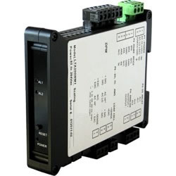
MLT-FR | 4-20 mA & Serial Data Output | Average Time of Periodic Events | DIN Rail Transmitter
The Micron Meter Time interval transmitter can transmit pulse width or time delay between individual pulses to a resolution of 0.2 µs for periodic events. It can also transmit average pulse width or average time delay between multiple pulses.
Time interval is measured between inputs on channels A and B. Timing starts when a pulse is applied to Channel A (selectable positive or negative edge), and ends when a pulse is applied to Channel B (selectable positive or negative edge). In case of a single pulsed signal, the A and B inputs can be tied together. A positive or negative slope may be selected to start timing, and the opposite slope must be selected to stop timing. Timing is achieved by counting 5.5 MHz clock pulses. Multiple integral time intervals are averaged over a gate time which is selectable from 10 ms to 199.99 s and also controls the maximum output rate.
The dual-channel signal conditioner used for pulse detection accepts inputs from proximity switches with PNP or NPN output, TTL or CMOS logic, magnetic pickups, contact closures, and other signals from 12 mV to 250 Vac. Jumper selections provide optimum operation for different sensor types and noise conditions. A built-in 5V, 10V or 24V dc excitation supply can power proximity switches and other sensors, and eliminate the need for an external power supply.
- 4-20 mA, 0-10V or -10V to +10V analog transmitter output, isolated, jumper-selectable and user scalable. All selections provide 16-bit (0.0015%) resolution of output span and 0.02% output accuracy of a reading from -99,999 to +99,999 counts that is also transmitted digitally. Output isolation from signal and power grounds eliminates potential ground loop problems.
- Serial communications output, RS232 or RS485 (half or full duplex), jumper selectable. Three protocols are user selectable: Modbus RTU, Modbus ASCII, or Custom ASCII. Modbus operation is fully compliant with Modbus Over Serial Line Specification V1.0 (2002). The Custom ASCII protocol is simpler than the Modbus protocol and is recommended when all devices are Micron units.
- Dual solid state relays, isolated, for alarm or control. Rated 120 mA at 130 Vac or 170 Vdc.
- Transducer excitation output, isolated. User selectable 5V@100 mA, 10V@120 mA or 24V@50 mA.
- Universal 85-264 Vac power. Low-voltage 10-48 Vdc or 12-32 Vac power is optional.
Easy Transmitter programming is via the Instrument Setup Software, which runs on a PC under MS Windows. This software can be downloaded from this website at no charge. The required transmitter-to-PC interface cable is available. (P/N CBL04).
![]() MLT-FR Time Interval Transmitter | Support Library
MLT-FR Time Interval Transmitter | Support Library
Data Sheet | User Manual