Your shopping cart is currently empty.
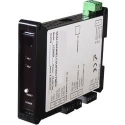
MLTE-FR | Ethernet & 4-20 mA Output | AC Phase Angle and Power Factor | DIN Rail Transmitter
Phase Angle Measurement
Phase angle in degrees indicates the phase lead or lag between two periodic signals of the same period, as determined from their zero crossings. These two signals will typically be the voltage and current applied to a load. As illustrated, the phase angle in degrees is +360*P1/P.
The Micron Meters Phase angle transmitter transmits the lead or lag in degrees from 0° to 360° between two periodic signals of the same period. In the illustration to the right, phase angle is 360*P1/P. The signals are applied to the Channel A and B inputs of the Micron dual-channel pulse input signal conditioner board. A resolution of 1°, 0.1° or 0.01° is selectable. Accuracy is 0.01% up to 100 Hz, 0.1% at 1 kHz, and 1% at 10 kHz.
Power Factor Measurement
The power factor of an AC power system is the ratio of real power in watts (W) divided by apparent power in volt-amperes (VA). For sinusoidal signals, power factor is the cosine of phase angle.
The Micron power factor transmitter computes power factor as the cosine of phase angle. Power factor readings can range from 1.000 to 0.000 with three decimal places and an accuracy of 0.1% for sinusoidal signals at 50/60 Hz power line frequency. While power factor is always positive, the meter artificially assigns a minus sign to power factor for negative phase angles, and it sets power factor to 0 for phase angles greater than 90°.
Designed for flexibility
Phase angle and power factor are determined by timing crystal clock pulses over a specified gate time which is selectable from 10 ms to 199.99 s. By selecting the minimum gate time of 10 ms, the update rate can be up to 20/s for 50/60 Hz AC line frequency. Improved accuracy is obtained by making the gate time long enough so that multiple cycles can be averaged.
Exceptional Accuracy and Stability. Micron transmitters determine frequency by taking the inverse of period as measured with a calibrated quartz crystal time base. This results in extremely accurate and stable 6-digit internal readings (±999,999 counts), which are then processed in software. The analog output is generated by an ultra-linear 16-bit (65,536 step) digital-to-analog converter (DAC) for 0.02% output accuracy. The update rate of the transmitter output is a programmed gate time + 30 ms + 0-2 signal periods. For a 60 Hz signal, the update rate would be 20 per second. Such fast update rates are ideal for alarm and control.
Standard features of Micron MLTE transmitters include:
- Ethernet I/O, isolated. Supported protocols are Modbus RTU and ASCII (tunneled via Modbus TCP) and Custom ASCII. The latter is simpler than the Modbus protocol and is recommended when all devices are Micron units. Note that RS232 or RS485 data I/O in lieu of Ethernet is provided by MLT Series transmitters.
- 4-20 mA, 0-20 mA or 0-10V analog transmitter output, isolated, jumper-selectable and user scalable. All selections provide 16-bit (0.0015%) resolution of output span and 0.02% output accuracy of a reading from -99,999 to +99,999 counts that is also transmitted digitally. Output isolation from signal and power grounds eliminates potential ground loop problems. The supply can drive 20 mA into a 500 ohm (or lower) load for 10V compliance, or 10V into a 5K ohm (or higher) load for 2 mA compliance.
- Dual solid state relays, isolated. Available for local alarm or control. Rated 120 mA at 130 Vac or 180 Vdc.
- Universal 85-264 Vac power. Low-voltage 10-48 Vdc or 12-32 Vac power is optional.
Discovery and configuration of the Ethernet Nodes is easily achieved with the Node Manager Software, and the discovered transmitters can then be programmed using the Instrument Setup Software. Both softwares run on a PC under MS Windows and can be downloaded from this website at no charge.
![]() MLTE-FR Phase Angle Measurement Transmitter | Support Library
MLTE-FR Phase Angle Measurement Transmitter | Support Library
Data Sheet | User Manual