Your shopping cart is currently empty.
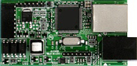
Ethernet-to-RS485 Converter Board for Micron's MM50 Series 1/8 DIN Instruments
Key Features
- Connects a host meter to an Ethernet LAN while also acting as a server
for up to 31 Micron devices on an RS485 network. - Includes an RJ45 jack for connection to the Ethernet plus an RJ11 jack for connection to the RS485 bus.
- Suitable for all 1/8 DIN Micron DPMs, counters, timers & remote displays.
- Complemented by Node Manager software which discovers Nodes and meters.
- Selectable baud rates to 19,200.
- Isolated from meter and power grounds.
 |
 |
 |
Description
The Micron Ethernet-to-RS485 Converter Board plugs into a host 1/8 DIN digital panel meter, counter or timer to provide a 10/100 Base-T Ethernet interface via an industry-standard RJ45 jack for that meter. It also provides an RJ11 jack for interface to an RS485 bus, which can support up to 31 Micron Meters equipped with Micron's RS485 interface board. That board features dual RJ11 connectors for RS485 daisy-chaining using commercial 6-wire RJ11 data cables, with no need for a hub.
Micron's Node Manager software is shipped on a mini CD with each Ethernet board. This free Windows-based application automatically discovers all Micron Nodes (or Micron Ethernet boards) on a LAN or WAN, plus any meters connected to the Nodes. These will be the host meter for Ethernet-to-RS485 converter board, plus any meters and transmitters on the RS485 bus. Node Manager software is also used to configure each Node, such as naming the Node and associated devices, entering email addresses for alarm notification and data requests, selecting the Node's time zone for time-stamping of streaming data, and setting communication parameters for associated meters. Please see our Ethernet Manual.
On a Wide Area Network (WAN), such as the Internet, the host computer is outside of the LAN and therefore must know the public IP address of the LAN router to discover the Micron Nodes. If the public IP address of the router is not known or becomes unknown because it is dynamic rather than a static, the host computer can accomplish the discovery by interrogating a Resolution Server computer located at our factory.
Built-in DHCP server capability allows Micron Nodes to constitute themselves into a network and be connected directly to a host computer when no router or dedicated DHCP server is present, as illustrated above. When a Node fails to find a DHCP server that responds to its request for a private IP address, it assigns one. When several Nodes fail to receive a Private IP address, they mutually agree to make one of the Nodes a temporary DHCP server that assigns a Private IP address to each device on the network.
Data can be sent by Micron Nodes in the form of real-time stream data, or in the form of emails. Accuracy of streaming data is ensured by filtering and by dual checksums. Emails can be sent in response to email requests from the host computer, periodically, or when devices encounter an alarm condition or go off-line.
The Modbus TCP protocol is fully supported. Conversion to Modbus TCP is provided transparently by Micron Nodes so that an Ethernet application program can use the Modbus TCP protocol while the meters use the Modbus RTU or Modbus ASCII protocol. The L-ASCII protocol, which supports up to 31 digital addresses, can also be used if the only devices on the data line are Micron meters.
Micron's Ethernet board can be used as an alternative to the server board for networking multiple meters. Each meter will then need to be connected to the network via an Ethernet router, switch or hub, and its own Ethernet cable.
Specifications
| Ethernet Board Specifications | |
|---|---|
| Data rates | 300, 600, 1200, 2400, 4800, 9600, 19200 bps |
| Devices per Ethernet line | 1 Node plus up to 31 on RS485 bus |
| Ethernet connector | RJ45 jack |
| Ethernet cable | 10/100 Base-T |
| Ethernet compliance | IEEE 802.3 |
| Devices per RS485 line | Up to 31 |
| RS485 connector | RJ11 jack |
| RS485 compliance | EIA/TIA-485 |
| Isolation | 250V rms working, 2.3 kV rms per 1 min test |
| ESD Protection | 15 kV per IEC 1000-4-2 |
| EMI Immunity | 10 V/m per IEC 1000-4-3 |
| EFT Protection | 2 kV per IEC 1000-4-4 |
| Short Circuit Protection | Continuous |
| Selectable Protocols | Modbus RTU, Modbus ASCII, Micron ASCII. |
Protocol Specifications |
(implemented on meter main board) |
| Modbus RTU | |
|---|---|
| Standards Compliance | Modbus over Serial Line Specification V1.0 (2002) |
| Data Formats (selectable) | 1. No parity, 8 data bits, 2 stop bits |
| 2. Odd parity, 8 data bits, 1 stop bit | |
| 3. Even parity, 8 data bits, 1 stop bit | |
| Applicable Interface Boards | Ethernet, USB, RS232, RS485, RS485 Modbus |
| Conversion to Modbus TCP | Automatic |
| Main Board Revision Level | Level 5 or above |
| Modbus ASCII | |
| Standards Compliance | Modbus over Serial Line Specification V1.0 (2002) |
| Data Formats (selectable) | 1. No parity, 7 data bits, 2 stop bits |
| 2. Odd parity, 7 data bits, 1 stop bit | |
| 3. Even parity, 7 data bits, 1 stop bit | |
| Applicable Interface Boards | Ethernet, USB, RS232, RS485, Modbus RS485 |
| Conversion to Modbus TCP | Automatic |
| Board Revision Level | Level 5 or above |
| Micron ASCII | |
| Data Format | No parity, 8 data bits, 1 stop bit |
| Protocol | Micron Micron ASCII |
| Applicable Interface Boards | Ethernet, USB, RS232, RS485, RS485 Modbus |
| Main Board Revision Level | Any |